Bad day, with hoses

May 25th, 2008

Today stated off well but ended poorly…

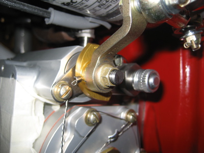
I wanted to use a restrictor fitting for the connection to the manifold pressure hose, to keep the #3 cylinder from running too lean if the hose breaks. But, Van's only sells a 45-degree restrictor which won't fit on my engine. I had to make my own straight restrictor by filling an AN816 fitting with JB Weld, waiting a day for it to cure, and then drilling a #60 hole through it. Turned out great:

Installed in the port on the #3 cylinder:

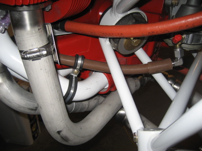
The manifold pressure hose attaches to the restrictor fitting, then sort of loops inward:

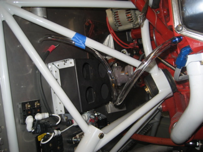
It's attached to the engine mount with adel clamps, and passes through a fitting I installed in the firewall near the brake fluid reservoir.

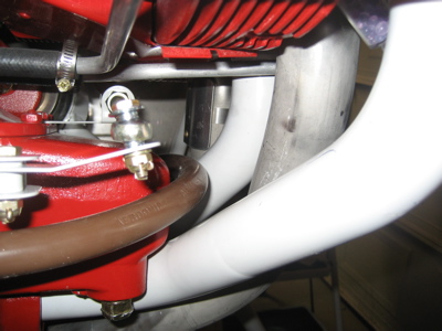
The hose that goes between the firewall and the fuel pump inlet is a tight fit, but it works. In this photo I'm using a bungee cord to teach the hose to follow a curve that keeps it away from the engine mount. A couple hours like that and it kept the right shape on its own.

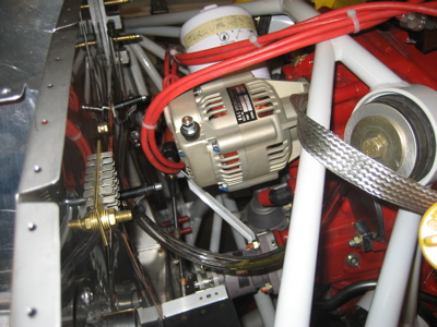
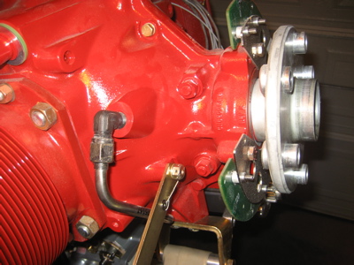
The oil pressure hose exits the right side of the accessory case, loops around to the left, and is secured to the top of the firewall with adel clamps.

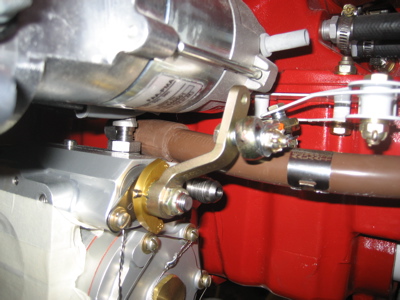
The oil pressure hose enters the transducer manifold (top of photo), as does the fuel pressure hose (bottom). Eventually there will be pressure transducers screwed into the manifold, and the unused holes will be plugged.

The fuel pressure hose runs down to a tee on the outlet of the fuel pump (brown hose in center of photo). Also visible in the background is the fuel pump overflow hose, which runs down to the bottom of the firewall.

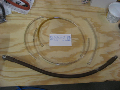
I have a policy that any hose that carries pressure should be professionally made and tested, but since the fuel pump drain hose doesn't carry any pressure and should rarely even have any fuel in it, I decided to make that one myself. This is Aeroquip 303 hose, using the recommended mandrel for assembly. It's a pain to do properly – I'm glad to leave making the proper hoses to the pros.

Of course, the plans call for the fuel pump overflow hose to be made from plastic tubing, but I thought that was cheesy. My hose is a little heavier but at least it won't melt/crack/etc. The hose runs down to an AN837 fitting that's adel-clamped to the engine mount, and thence a length of aluminum carries the fuel overboard and out the back of the cowling. I drilled out one of the rivets on the firewall flange and used it for a screw and clamp that secures the tubing.

Here's where it all went off the tracks… while installing the very last fitting, the upper one for the fuel pump drain, I accidentally cracked the fuel pump housing:

Another photo with different light. I guess it doesn't take very much torque on a steel fitting to ruin a thin cast-aluminum housing.

After stewing about it for a while, I decided that the fuel pump has to come off to be rebuilt. That meant I had to take off most of the hoses I'd just spent hours installing. I also had to take off the magneto and loosen the prop governor cable bracket just to be able to get at the fuel pump bolts. Nothing on the engine is easy to work on!

After a couple hours of bad language, the fuel pump is now removed from the engine. Hopefully repairing or replacing it won't be too expensive.

I also had to mow the hateful lawn, and the new Indiana Jones movie was not very good, and now I have a headache, so overall this day has been kind of a dud.

Fuel hose

May 17th, 2008

Believe it or not, it took me an entire afternoon to install the hose that goes between the engine-driven fuel pump on the back of the engine and the fuel injection servo up front. This seemingly simple task was greatly complicated by clearance problems and lack of space to work in (is this starting to sound familiar?). You want the fuel line to be far away from the hot exhaust pipes, but the ideal routing – up over the "wing" of the oil sump – is blocked by the mixture bellcrank. So, I had to play with various routings of the hose until I could find a way to get it as far away from the exhaust as I could, while still staying clear of the mixture linkage when it's in the idle cutoff (worst case) position.

Since the hose is right there, I put some additional heat shields on the exhaust pipes to keep the fuel line cool. In this photo you can see the somewhat circuitous routing the hose takes, as it exits the fuel pump, crosses under an engine mount tube (the photo doesn't show it, but there's an inch of clearance there) and then climbs up away from the exhaust pipes. A pair of back-to-back adel clamps, shown here partially obscured by the exhaust, secures the hose to the #4 intake tube. I ended up with at least an inch of clearance between the heat shields and the hose. By the way, all my fuel/oil hoses are Stratoflex 124J assemblies with integrated firesleeve, made to my specifications by Precision Hose in Tulsa. Good customer service and good prices too.

These clamps were a giant pain to install, because the normal bolt-flinging properties of the adel clamps were magnified by the almost complete lack of access to the area where I wanted to put them. I managed to scrape a bunch of paint off the #2 and #4 intake tubes, but it's all cosmetic stuff.

I need to do better than one hose per day if I'm ever going to finish this thing.

Fuel flow sensor

May 4th, 2008

If you choose to research the topic obsessively, as I have been doing lately, you'll find that there are about three locations where people have been mounting the fuel flow sensor, and everyone thinks the way they installed theirs is best. You can put it on the cabin floor downstream of the electric fuel pump, near the engine between the mechanical fuel pump and fuel injection servo, or in the line between the fuel servo and the fuel distribution spider on top of the crankcase. I accept the argument that your fuel flow readings will be more accurate the farther downstream your sensor is placed, but there are also vibratory and thermal factors to consider when mounting a somewhat delicate sensor in the harsh environment of an engine compartment. After a weekend of head-scratching, I couldn't settle on a location forward of the firewall that I found completely satisfactory, so I gave up and elected to mount my flow sensor on the cabin floor. I can live with the fact that I may get inaccurate readings when the electric fuel pump is turned on, but that will only occur for a few minutes per flight. There is theoretically an increased chance of vapor lock as a result of adding another restriction upstream of the mechanical fuel pump, but I don't know of any evidence of this actually happening in real life (and if it does, I can still turn on the electric pump). There's also the fact that I put the flow sensor on the cabin floor in my last airplane, and it seemed to work fine.

Anyway, end of rationalization section. I pulled all the fuel plumbing out of the fuselage – it's easier than it sounds: you only have to undo three flare nuts and four screws and the whole works lifts right out.

I cut the line that previously went from the electric fuel pump outlet up to the firewall, re-flared it, and installed the fuel flow sensor.

The sensor body is partially tucked under the mounting plate, so it won't hit the fuel pump housing. It's not attached to anything, just sandwiched between the mounting plate and the floor. I stuck some foam weatherstrip material to the bottom, to hopefully isolate it from exhaust vibrations coming up through the floor.

With the flow sensor spliced in, the fuel line runs up to the firewall as before. Notice that this location satisfies the manufacturer's recommendation to give the sensor 5" of straight line on both the inlet and outlet sides, which is much more difficult on the other side of the firewall.

The housing fits without hitting the sensor or any of the plumbing:

Hose measuring

May 4th, 2008

Matittuck included a hose to go from the mechanical fuel pump on the back of the engine up to the fuel injection servo on the front. Here I'm test fitting it to the fuel pump outlet, and I've clamped it to the #4 cylinder's intake tube with adel clamps to keep it away from the exhaust:

The clearance between the hose and the #3 exhaust pipe is not much more than an inch, but there doesn't seem to be anywhere else for the hose to go – the mixture bellcrank gets in the way.

The included hose is too long by a couple inches (it's supposed to attach to the silver inlet port in the middle of the photo). I'll have to have a shorter one made up.

I bought some cheap plastic tubing from the hardware store and used it to measure for the other hoses I'll need to have made, without expensive guessing. Here's what the hose between the firewall and fuel pump inlet will look like:

Only somewhat visible here is the mockup of how the oil pressure hose will go:

Here's the stand-in for the manifold pressure hose:

I ended up with templates and measurements for five different hoses (I forgot to take a picture of the faux fuel pressure hose).

While I was messing around with the fuel servo, I replaced the nyloc nut on the mixture shaft with an all-metal locknut:

Alternator belt

May 3rd, 2008

There's a bolt at either end of the alternator tension arm, both of which need to be safetied. Some folks use one long length of safety wire between the two bolts, but that seems like it would be a pain when the belt inevitably wears out (since you need to loosen the bottom bolt to replace the belt). I also didn't want to just loop safety wire around the arm itself, since it would eventually vibrate and dig a groove into the steel.

So, I came up with what I think is a clever way of safetying the two bolts… first I drilled a pair of #30 holes in the meaty part of the arm:

Then I grabbed some #4 steel tinnerman washers and 1/8" steel pop rivets:

When riveted to the arm, the washer sits up above the surface just the right height to capture a loop of safety wire. The wire then bears on the steel pop rivet stem instead of wearing a groove in the arm.

With the ring gear removed, it's pretty easy to safety the upper bolt.

After putting on the belt and adjusting the tension, the lower bolt gets torqued and safetied in the same manner:

For future reference, the belt that seems to fit the best is a Gates 7360:

I tried a 7355 and it did fit, but it was very tough to install. I'll use the slightly longer belt unless I end up having clearance problems between the alternator and cowl.