Fuel hose

March 9th, 2013

For years I've been looking at the hose that carries fuel from the firewall to the engine-driven fuel pump, wishing it wasn't so close to the engine mount. Finally I decided to do something about it. I replaced the straight fitting at the pump with a 90-degree elbow, and took the hose to a local aircraft hydraulic place to get it shortened by two inches.

Now there's plenty of clearance between the hose and the engine mount. It's a little tight between the hose and the starboard exhaust pipe support, but I can tweak that part's position when I put the exhaust back on.

Another view looking up from below. The location given in the plans for the bulkhead fitting that brings fuel through the firewall is plain wrong, if you ask me. At least on my airplane it's very close to the starter solenoid, the resulting hose routing is problematic (see this post), and it's pretty difficult to get a wrench on the hose end nut. A better location would be straight below the heater air valve – you can see in this photo that it's completely open, and the hose routing from the firewall to the fuel pump would be very straightforward when using a 90-degree elbow on the engine side. Maybe they don't have you drill the hole there because they're reserving room for the nosegear weldment, but my airplane doesn't have one of those. Oh well, yet another thing to file away for next time.

Remote transponder

February 27th, 2013

I decided to sell my panel-mounted transponder and replace it with a remote-mounted unit instead. This is the GTX 23ES:

The unit itself is a faceless silver box – instead of pushing buttons on the transponder's front panel, you control it through the screen of your G3X system. It mounts in this sheet-metal tray, which I now have to find a place for.

The only practical place left in the airplane where I can mount something this size is the area under the baggage compartment floor on the passenger side of the fuselage. Needless to say, I'm glad I made my baggage floors removable.

The piece of aluminum angle shown here is riveted to the inboard floor rib with countersunk rivets, and it will act as a little shelf for the transponder tray to sit on. Some of the open holes visible in the rib are for tie wrap anchors that I temporarily removed to give myself space to work, but some are from little brackets and other things that I've since removed. This particular area of the airplane has undergone more changes than almost any other part, as I've installed various pieces of equipment and then later changed my plan and removed them in favor of something else.

Four pieces of angle plus some rivets became a pair of T-brackets, seen here riveted to the outboard floor rib. Keep reading to see what these are for.

I fabricated these two identical mounting braces out of some more aluminum angle. The mill was handy for removing excess material where it wasn't needed.

The braces attach to the transponder tray like so:

Closeup detail of how the braces attach to the tray, using #6 screws in the countersunk holes that are thoughtfully provided:

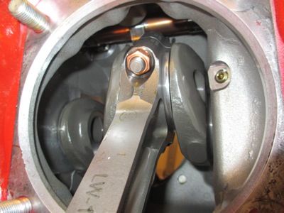
Here's how it all goes together. The transponder is oriented with the connectors facing towards the nose of the aircraft. The braces stay permanently attached to the tray, the tray sits on the longitudinal angle (not visible) and the braces are fastened in four places to the T-brackets and the inboard floor rib. It's kind of an odd setup, but it fits in the available space and is quite sturdy. Just as important, it is all fairly easy to remove if required.

Wiring… power and ground, RS-232 to the GSU 73, ARINC 429 to the two 430W's for TIS-A traffic display, and RS-232 for GPS position data from 430W #1 so I will be ADS-B Out compliant.

Wires routed and secured, all neat and tidy:

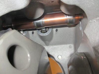
The transponder antenna coax carries high-power RF and shouldn't be routed with any other cable bundles (so says the install manual, anyway). I ran it inboard to the center tunnel, aft, and back outboard again to miss the elevator bellcrank on its way to the antenna. It's tie-wrapped to the floor rib with the usual plastic cable anchors.

You may have wondered earlier why I removed material from the middle of the mounting braces. If you look at this photo you can see that It's simply to prevent creasing the baggage compartment floor if I put something heavy on it (such as my knee!) that causes it to flex downward between the floor ribs. Well, it probably saves a few grams of weight too.

The overhead view shows why I had to make the tray removable, instead of permanently mounting the tray and just sliding the transponder in and out – no room! The under-floor avionics bay is physically not long enough to allow the transponder to be removed from the tray, even if I'd scrunched up the wiring and mounted it as far forward as humanly possible. So, to remove the transponder I'll have to undo four fasteners, lift the tray out of the floor, and then remove the transponder from the tray. I shouldn't have to do this too often, so hopefully it won't be too inconvenient.

Everything worked on the first try – after a few keystrokes for configuration, the transponder controls popped up on the PFD.

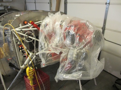
The only thing left to do on the transponder is to finish securing the antenna coax and connect it to the antenna on the belly. I'll tackle that eventually when I get around to venturing into the tailcone to finish up all the wiring back there. Right now that area is in a state of… let's go with "disarray".

Oh, you may be wondering why I decided to go to all this trouble in the first place. Why remove a perfectly good transponder from the panel just to put in a different one that's mounted somewhere else? Naturally, it was to make room in the panel for another toy… just what kind, I'm not telling yet.

Installed new cylinders

February 10th, 2013

After an unexpectedly long delay – due to schedule issues and also because ECI didn't send me all the expected parts on the first try – I finally managed to get my four new engine cylinders installed.

The cylinders are mounted and torqued, the pushrods and rocker arms are in, the oil drain tubes are back on, and the fuel injection lines are reinstalled and clamped. The intake and exhaust pipes are still off, since I want to get the EGT and CHT probes installed before I put them back on for good. And the rocker covers are not on yet because I ran out of steam and got tired of standing in the cold garage.

Grey cylinders with red pushrod tubes and crankcase is kind of a cool color scheme. Can't order 'em that way.

While I was complying with SB08-1, I also took care of SB12-1 by installing new stainless parts for the pushrod shroud tube retainer spring and lock tab.

Guiding me through this whole adventure was local engine guru Jerry Gippner, who taught me a lot about engine maintenance in the process. I think I could probably do it again on my own next time, so thanks Jerry for the education!

Next: Reinstalling baffles and other engine parts, hopefully for the last time (for the foreseeable future anyway).

Removed engine cylinders

January 5th, 2013

One of the things I've been putting off for as long as possible is dealing with SB08-1, the dreaded ECI service bulletin. The gist of it is that if you are unlucky enough to have a cylinder that came from a bad batch, it must be replaced with a new one, lest it develop a crack in-flight with spectacular and exciting results. Imagine how lucky you have to be for all four of your cylinders to be bad, like mine are! Fortunately I was able to work out a warranty deal with the company, but it's still going to be an expensive fix. At least I'll come out ahead of where I'd be if I had to buy four new cylinders at full retail price.

I waited until I couldn't make any further progress on the engine without starting to attach things semi-permanently, then finally gritted my teeth and started unbolting things. I took off the baffles, dropped the exhaust (and sent it back to the manufacturer to fix a different potential cracking issue), pulled the spark plugs, and so forth.

One of the many piles of stuff that came off the engine:

I've owned and maintained Lycoming engines before, but I've never done any serious maintenance like removing a cylinder. I decided to hire out the job to a local A&P, from whom I learned a lot about how it's done. Definitely worth the cost of hiring a pro to show you the ropes the first time when you're working on an engine that costs as much as a nice new car. But now look how sad it looks with the jugs removed:

Four bad cylinder assemblies, ready to be shipped back to where they came from. If you've never seen an air-cooled aircraft engine cylinder up close, these are about the size of a gallon of milk (I guess that's why they call them jugs?) and weigh maybe twenty pounds apiece. I saved the valve covers, pushrods, rocker arms, injector nozzles, and wrist pins – everything else including the pistons and rings goes back and gets replaced with new parts.

Amazing how many little things have to be removed before you can take the cylinders off:

On the bright side, pulling the cylinders gives me a chance to look inside the engine for corrosion. I was slightly worried that some internal rust might have started during the (sadly) extended period the engine has been sitting in my non climate controlled garage, but happily everything I can see inside the engine looks shiny and new.

The ever-critical camshaft looks great as well. Once the cam starts to go, you're looking at a five-figure engine teardown. Luckily that date appears to still be a long ways off.

I boxed up the old cylinders and sent them on their way. Meanwhile I threw a tarp over the engine to keep stuff from falling into the open cylinder holes while I'm waiting for new jugs to arrive.

Although it is without a doubt an unfortunate backwards step, this chore is actually also a bit exciting, since it means that once the new cylinders are installed, I'll be able to start attaching things to the engine for the last time. Think positive

Red beacon

October 28th, 2012

I've been planning to put some kind of red flashing ground-recognition beacon on the airplane all along, and this weekend I finally got around to making it happen. For years I've been pondering exactly what kind of beacon I need and where to mount it – see here and here for details of previous plans that didn't get completed, plus thoughts on red beacons in general. What ended up working in my favor is the fact that, while I was trying to figure out what to do, the state of the art in LED technology has advanced to the point where it now makes more sense to use LEDs rather than xenon strobes or halogen flashers for this application.

The particular unit I picked is the Vertex LED lighthead by Whelen. These guys are known in aviation circles for making certified strobes and nav lights, but they make lots of automotive products too. This one is designed to work as a warning light for a cop car or other emergency vehicle, but it happens to also be the perfect size for an airplane too. Here's a photo I grabbed from the internet since I forgot to take a "before" shot prior to getting started:

I played with various mounting positions until I decided which one I liked best – it turned out to be the top of the tail, just like on your grandpa's Cessna. Then I got out the rudder cap and started cutting away at it with a unibit and Dremel tool.

The light will be held in place by two little pieces of scrap angle that will attach to the inside of the rudder cap.

A view from the bottom side. The beacon heatsink just fits into the widest point of the rudder cap.

That has the added advantage of putting the beacon about halfway back from the leading edge of the vertical stabilizer – farther back than on a Cessna – where the light shining directly forward will be blocked instead of getting into the cockpit and annoying me by glaring off the instrument panel.

The circuit board inside the beacon is flush with the top of the rudder cap. Now we just need to do something about the exposed shoulders of the heatsink sticking out into the breeze.

I covered the beacon with saran wrap and then laid up several plies of glass tape over it in a smooth shape:

It's a little late in the season to be doing fiberglass work – i.e. the temperature is a bit low in the garage – but for small projects you can cheat and use a heat lamp to get the resin to cure in a reasonable amount of time.

After sanding the initial layup, I installed the beacon again and followed up with a flox/cabosil mixture to build up the contour and give me a nice sharp edge around the opening for the lens.

I also laid up some flox inside the rudder cap to give the body of the beacon a nice solid shoulder to sit on, as well as thickening up the inside of the lens opening to avoid having a knife edge there.

After letting that cure and sanding it back down, the general shape of the "bump" for the beacon was basically done.

I applied one more coat of dry micro with a squeegee to fill in the low spots, then sanded it smooth.

A quick spray of primer dressed it right up. I'm quite happy with how the shape turned out. There are some small surface imperfections but I'll let the painter deal with those.

The beacon lens is very low profile. I still need to countersink the mounting holes in the sides, but that can wait until I get back the drawer full of #4 tinnerman washers I loaned out.

Now that it's all sanded smooth and blended in, the slight swell for the beacon is hardly noticeable:

What's that, you say you want to see my new rudder-mounted ground recognition beacon in operation? Very well:

It's hard to properly capture with the camera, but trust me, this thing is plenty bright.