After getting deburred, the rudder skin and stiffeners are dimpled and primed:


Rivet tape holds the rivet heads in place on the outside of the skin for back riveting:

I ground off part of the white plastic collar on my Avery back rivet set to let it sit down squarely around the rivet without interfering with the stiffener flange.

Here the stiffeners have been back riveted to the rudder skin. The rivets themselves turned out great, and back riveting is really easy. The only bummer thing was the way the edges of the back rivet plate left marks on the skin. About three quarters of the way through I decided to put some blue masking tape around the perimeter of the plate, which made it stop marking up the skin – wish I'd done that to begin with. Oh well, they're very light marks and the paint will cover 'em up anyway.


Then I moved on to the rudder skeleton. First they have you drill out the 3/8" hole for the lower pivot bearing, and fit the rudder horn.

It's hard to see, but there is a little shim in there that I had to fabricate from 0.032" stock:

Reinforcement plates get match drilled to the spar at the three hinge points:

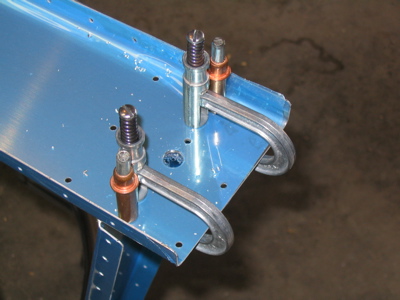
Then the tip and counterbalance ribs get fluted and match drilled to the spar. This is one solution to the problem of holding a rib in place while you pull out one of the two clecoes holding it to the spar in order to enlarge the holes – two pieces of scrap angle and some clamps keep it from moving around:

Here the counterbalance skin is being match drilled. This skin along with the spar, tip rib, and counterbalance rib forms a little box where the lead counterbalance weight will live.

The next step is to cleco on the rudder skins and match drill everything, including the trailing edge wedge. Hey look, a control surface!

Then they have you modify the rudder horn brace by cutting off part of the "ears" (already done in this photo).

Then the brace gets match drilled to the spar and rudder horn.

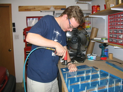
This was a productive day. Here's one more photo – "Self Portrait With Rudder".