Archive for the ‘Wings’ Category

Wing attach details

Sunday, July 4th, 2021

With the wings temporarily fitted to the fuselage, there are a handful of tasks to accomplish before removing them one last time. Careful planning will prevent too many on-off-on efforts – let's hope I didn't forget anything!

First up is the wing root faring, which will be screwed to nutplates all along the inboard edge of the wing. I was pleasantly surprised that the pre-punched holes lined up pretty well, although there is still some fiddling required (and watch the edge distance on the tank skin!).

The gap here is not perfect yet, but it's good enough to drill the fastener holes, which is my main concern. Once the wings are on permanently, I'll scribe and trim the edge of the root fairings to achieve a uniform gap into which I can install a rubber trim strip.

I drilled all the wing root fairing attach holes up to #19. The job of dimpling the holes and installing the nutplates will have to wait till the wings come off again.

I fitted the tank attach brackets, which required a few small tweaks to the bend angles, and drilled the bolt hole in each tank's mounting ear. When the wings are off I'll install a nutplate where this temporary bolt is:

Wing fitting

Friday, July 2nd, 2021

With all the remaining work on the wings completed satisfactorily, I summoned a friend to help me fit them to the fuselage. It was actually no big deal to mate the wings to the fuselage, although it's definitely a two-person job. After inserting the first wing spar into the center section, I climbed inside and drove in two 7/16" drift pins. Then we repeated the process for the other wing, and voila:

I removed the tailwheel and lifted the tail onto a table, adding wood shims underneath to level the fuselage at the longerons. Just for safety I strapped it all down, don't want to accidentally drop the tail on the ground.
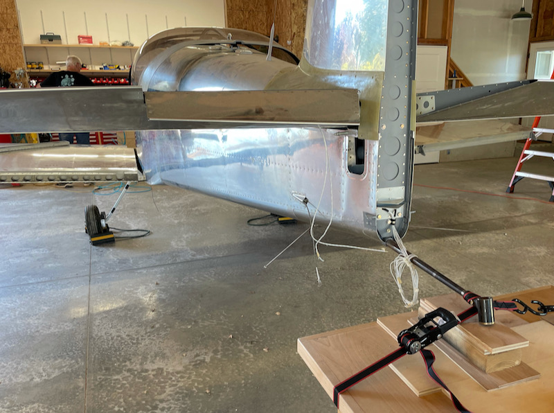
I basically followed the factory guidance to make sure the wings were aligned in various directions. Here I'm using a series of plumb bobs to check the sweep angle:
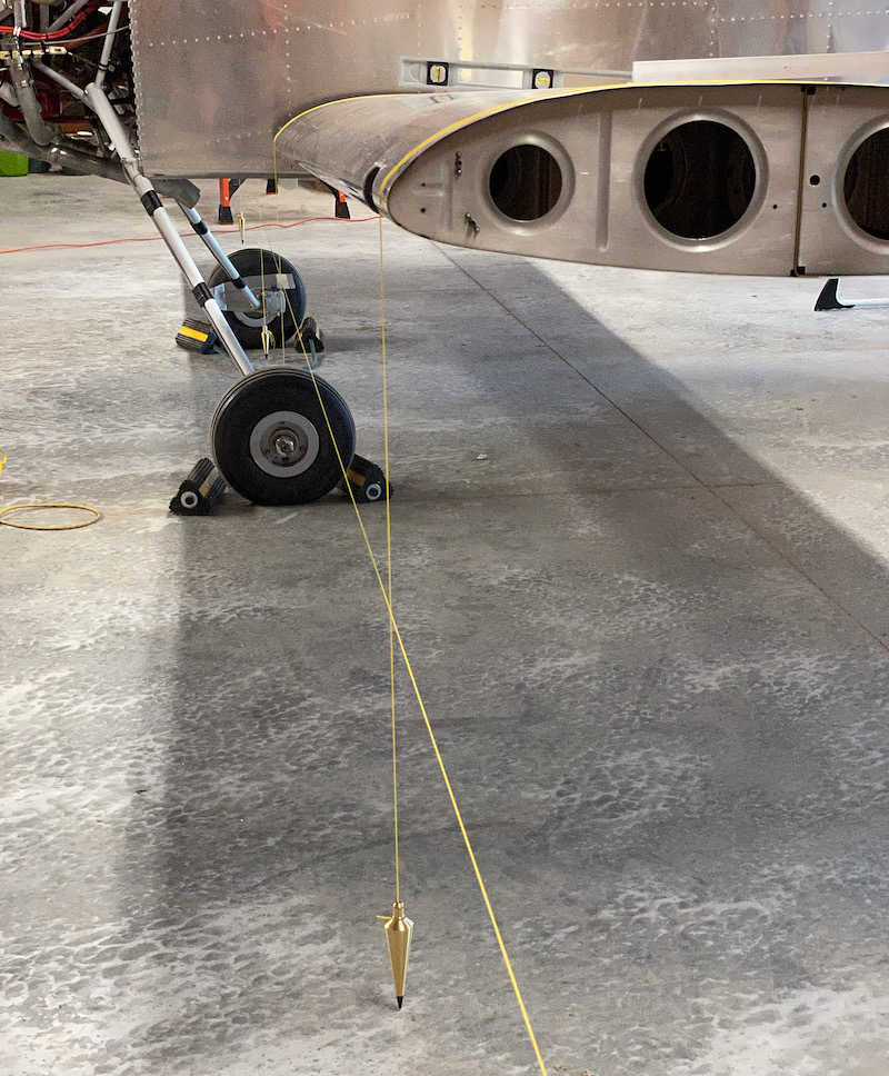
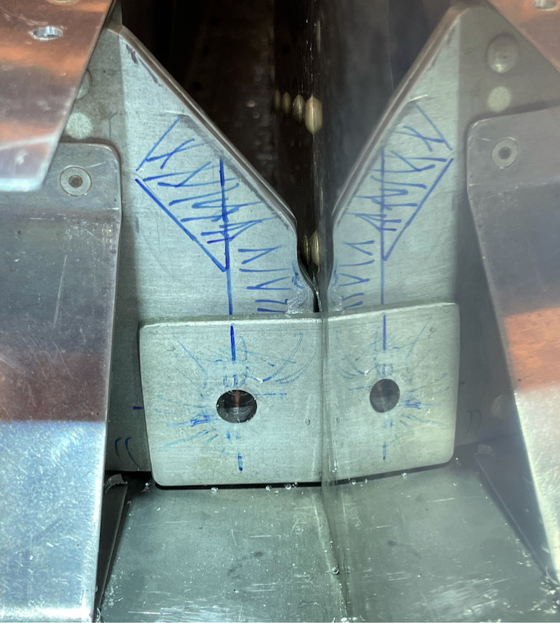
The initial fitting showed a small amount of forward sweep on both wings, and almost zero margin laterally for edge distance in the rear spar (notice how the vertical no-go lines here are almost on top of each other). The issue for both wings was that a single round-head rivet was preventing the wing from being inserted fully. I know this is a common issue, so if you're reading this before you build the fuselage, do yourself a favor and put a flush rivet there instead.
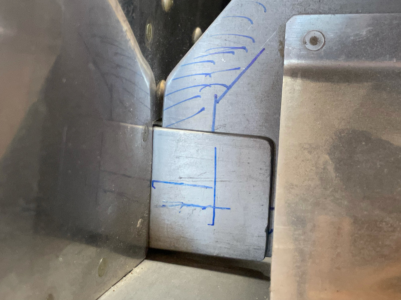
We then I removed the wings again and I ground a relief notch in each rear spar – fortunately no edge distance worries in this location:
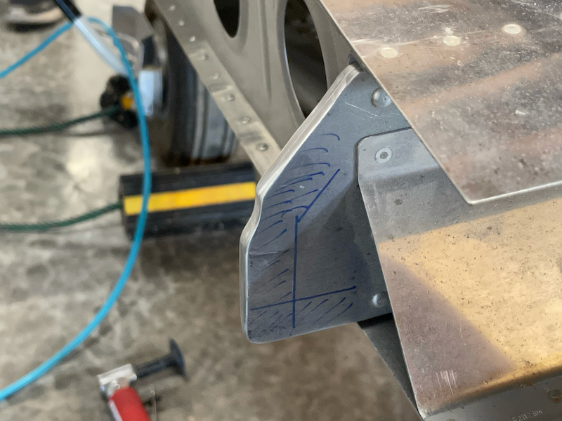
With the wings back on the fuselage, the rear spars can now be fully inserted, and the resulting sweep angle is essentially nil, a perfect result. And although the margin for edge distance still isn't huge, it's no longer zero:

After thoroughly checking the wing incidence using the prescribed jig and a digital level, I took a deep breath and drilled a pilot hole for the rear spar bolt:
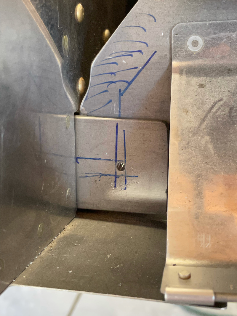
Moving over to the other wing, this is the procedure I followed for drilling these holes. After checking and re-checking the incidence and edge distance, I marked and center punched the hole location, then spot-drilled a divot in the desired location. This isn't a full through-hole, it's just deep enough to center the drill bit in for the next step.
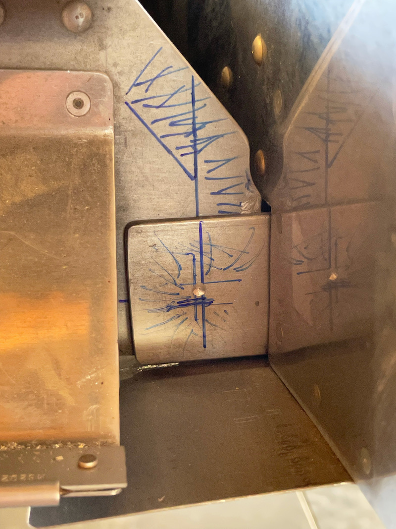
Using the divot as a guide, I used a bit to center my drill jig, then clamped it in place. There's a 1/8" spacer in there to allow the drill jig to sit level.
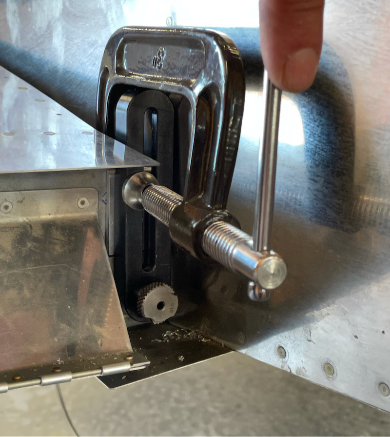
I drilled the initial 1/8" pilot hole, re-checked the edge distance, and then used progressively larger bushings to enlarge the hole without moving the jig. This resulted in a very straight and accurate hole.
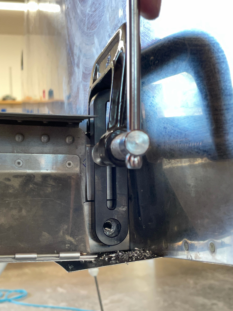
The final drill size was a size N (.302") followed by a final pass with a .311" reamer.
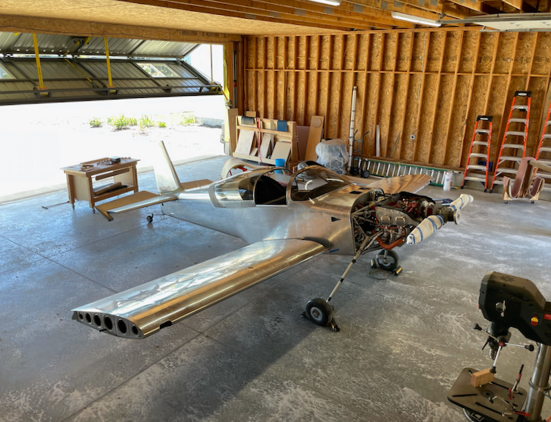
The wings will have to come off at least once more before they get installed for good, and there's still a huge amount of work remaining, but it's wild to walk through the hangar and suddenly see the airplane looking properly airplane shaped!
Roll servo

Sunday, June 20th, 2021

I'm now trying to wrap up a number of to-do items on the wings, one of which was to install the roll servo (again). Doing this while working through the inspection hole is not as terrible of a job as it seems, as long as you have skinny arms and you can work by feel. I torqued all the servo mounting hardware and the bellcrank pivot bolt, but I left the servo pushrod hardware loose since its length will need to be adjusted later.

I ran new wires through the wing for the servo, and used a couple of adel clamps to keep them securely constrained so they won't get tangled up with the flight controls:

The pushrod hardware called out by Garmin makes for tight clearance between this bolt and the servo housing, but it's probably adequate. I'll check this again when I'm doing the final rigging and control checks.

To test the new servo and wiring I wheeled the wings over to the fuselage and made some temporary connections with alligator clips:

Technically, the wings are now "connected" to the fuselage!

All is well with communication to the roll servo, so I can check this off my list:

Flap motor wiring

Sunday, July 19th, 2009

Since I had one of the required components in hand already, I decided to also work on the flap motor and associated wiring this weekend. Here I've mounted the flap positioning system control box on the new backrest brace:

Here's another view to show how it stands off from the underlying rivets, thanks to a few nylon washers. That dimpled hole in the foreground is for mounting an adel clamp.

As I previously threatened, I cut the wire harness between the control box and position sensor and crimped on some connectors. Now the motor and control box don't have to both come out of the fuselage at the same time.

Since the flap motor is now no longer permanently tethered to anything else, I couldn't think of a reason not to (semi) permanently attach it to the flap actuator channel. This photo is proof that I did put the cotter pin in:

Then I spent several hours running wires to the flap switch and pulling wires back to the flap motor. Properly bundling and securing new wires takes me about ten minutes per linear foot per wire (longer if I have to drill new grommet holes or install new clamps or tie wrap anchors) so consequently this took all afternoon. I left the flap switch hanging from the panel for now, since there's no need to go to the trouble of bolting it in place for an electrical test.

Once I had all the connectors installed, I plugged it in and gave it a floor run… it works! Bump the switch, and the flaps move one notch up or down. Nice. I'll clean up the wires in a future work session.

Fuel tank manometer test

Saturday, September 22nd, 2007

John loaned me his fuel tank leak testing kit a couple weeks ago, and I've been using it to do some extended testing of my fuel tanks. It's a simple water manometer that plugs into the tank outlet – you cap off the vent line and then use a Schraeder valve threaded into the drain flange to pressurize the tank.

I filled the first tank to 27 inches of water, which is about 1 psi, and marked the height of the water column.

Then I left it alone for a week. The water level fluctuated up and down with local pressure and temperature changes, but at the end of a week the tank was still holding approximately the same amount of pressure. After that I did the other tank, and it tested fine too. Hooray!

You can buy the fittings to make one of these setups from Van's, but you have to supply the plumbing and yourself (or borrow a buddy's).