Archive for the ‘Fuselage’ Category

Replaced brake pedal bolts

Thursday, February 1st, 2007

I crawled into the fuselage and replaced each of the pairs of bolts upon which the brake pedals pivot, with a single AN3-60 bolt that goes all the way through both sides of the pedal. As promised on the VAF forums, this really does make the brake pedal pivot more smoothly and want to bind up less. But let me tell you, this would be sooo much easier to do before the pedals are installed in the airplane. There's not a lot of access under there to fiddle around with washers and cotter pins, but I managed to get it done.

Something closer to an AN3-56 would have worked even better here, but only -55 and -60 lengths are commonly available. I just put a few washers under the bolt heads and nuts. Done deal.

Fitted air vents

Sunday, January 28th, 2007

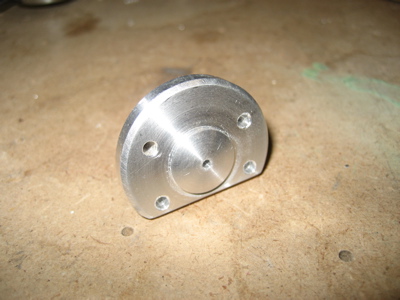
Since I was already working on stuff in the forward fuselage, I decided to tackle the air vents today. The air enters the cabin through plastic inlets that are attached to the fuselage side skins. Some people use only proseal here, but I decided I wanted to also use a few rivets in order to keep the inlets from coming loose down the road. Since the plastic they're made of is too thin and brittle to support a rivet directly, you need to find a way to beef up the inlets and give the rivets something to grab. I started by tracing the outline of the inlets onto some alclad sheet:

After much cutting, trimming, sanding, shaping, and deburring, I had a pair of aluminum doubler rings that were custom fit to the inlets.

The vent kit comes with a template, upon which I marked my rivet locations, then transferred them to the fuselage skins with a punch. Then I drilled #40 holes in the marked locations.

I carefully held the first inlet in place and drilled through the holes into the flange of the inlet. Careful measuring and marking pays off here. However, don't become so fixated on getting a good fit that you drill a hole in your finger, because trust me it is painful! Uh, I mean I heard that it is. From this one guy I know. Yeah.

Then I transferred the hole locations into the doubler ring. Repeat for the other side and the fitting of the vents was completed.

Before putting away the tools, I unclecoed the subpanel and its ribs and removed them from the fuselage in preparation for a little chore I need to do when I get a chance…

Installed static ports

Sunday, January 7th, 2007

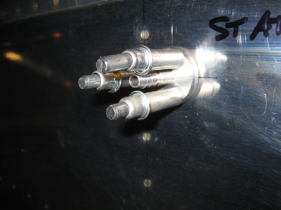
I decided to ditch the SafeAir static ports and picked up a set of Cleaveland ports instead. These have a wider protrusion that's more like the rivet they'll be replacing.

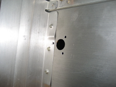
From the outside of the fuselage, I enlarged the pilot hole to 1/2" and drilled the three holes through which each port rivets to the fuselage.

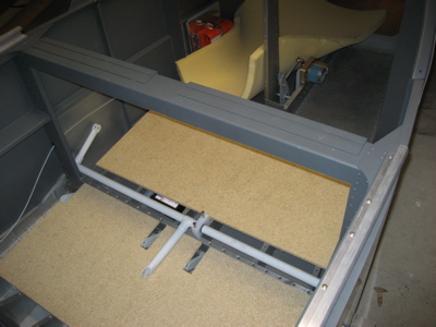
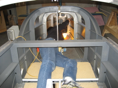
To rivet these things in place, I had to crawl way back into the tailcone. To keep from banging up the airplane (and myself) I made these temporary floorboards out of thin particle board scraps I had laying around, and threw down a square of foam rubber too.

Here goes…

Ugh, this is no good. Since the Cleaveland ports are much bigger than the Van's rivet, if you use the plans location for the static ports you'll end up with the port overlapping the F-707 bulkhead flange. Crapola. If you're going to use aftermarket static ports, do yourself a favor and move them about 3/8" forward of the location called out in the plans.

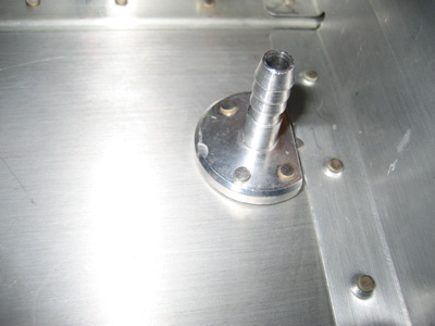
Back out on the workbench, I decided to modify the static ports by cutting off a section, then drilling two more holes symmetrical with the remaining two.

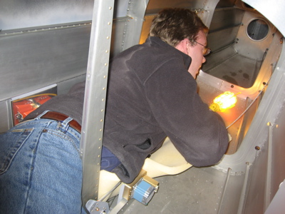
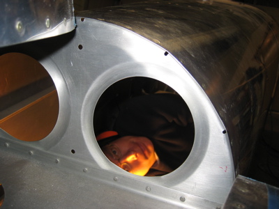
Back into the fuselage again. Mary took a bunch of photos of me doing this. Trust me, it's less fun than it looks.

I backdrilled two more mounting holes per port, then we teamed up to dimple the holes using the pop rivet dimple dies. But first, Mary had to do the old "finger through the F-773 fuselage skin" trick.

It took a few more trips into the bowels of the airplane to get the ports riveted on for good.

There, all done. We put a short filler rivet in the unused fifth hole on each side.

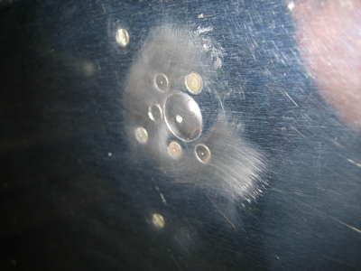
From the outside, the new static ports look not too bad. Mary slipped with the rivet gun and slightly dinged this port, but I think it will be hidden by paint eventually. The swirl marks are from me doing a bit of polishing of a rivet head that was a few thousands proud of the skin.

I think I was in and out of the fuselage a total of six times today. I still need to run the plumbing back to the ports, but I need to pick up some little plastic clamps first.

In retrospect, I probably could have made the simple pop-rivet-as-static-port method called for in the plans work just fine, and it would have been a lot less work and expense. But then I just wouldn't be me.

Nuts and tires

Saturday, January 6th, 2007

Avery has a really neat RV jack stand kit that makes it a lot easier to jack up the airplane. It requires you to modify your axle nuts in a manner that I was too lazy to do, so I paid a couple extra bucks to have them send me a pair of wheel nuts that already had the proper holes cut and slots milled into them. All I had to do was rivet the nutplate onto each one.

I also received my tires from Desser Tire today. These are Michelin Aviators with Airstop tubes – much higher quality than the tires Van's supplies (which I deleted from the finish kit). I used these on my last RV and they lasted forever and hardly ever needed airing up, which is a lot more than I can say about the cheapo Van's-supplied tires and tubes that airplane previously had. I figure it's worth it to spend the extra money here.

And for some reason, my cat loves them:

Mounted ELT

Sunday, December 31st, 2006

The plans that come with the ELT mounting bracket are similar to the plans for the RV-10 and the new prepunched RV-8. Compared to the vague and confusing RV-7/9 plans, the new style is practically a comic book that shows you how to pound airplane parts together. You RV-10 builders don't know how easy you've got it. (Note to pre-quickbuild RV builders: Please don't email me with stories about how you had to mine your own bauxite from the Earth's crust and turn your own rivets on a lathe – I already know the kit could be a lot worse.)

The rivets that attach the lower flange of the ELT bracket to the bottom J-channel stiffener are really hard to get to. In order to drill the holes, you need to use a 1/2" stubby drill bit in an angle drill. I also had to use a mirror just to figure out where the prepunched holes were.

Here's the bracket with all the holes drilled:

After all the holes were drilled, I pulled the bracket out of the fuselage, deburred it, primed the back side and the mating flanges, and installed the nutplates. You actually only need to put nutplates in four of the eight prepunched positions, since half the holes are for the ELT and the other half are for mounting a strobe power supply. However, I figured that since I won't be able to remove the bracket later, and I'm not 100% sure I won't need to mount something else here instead, I might as well go ahead and put nutplates in all eight holes. I may thank myself later, who knows.

I used K1100 dimpled nutplates in the four holes that the ELT attaches to, so I could also dimple the ELT mounting tray and not have to worry about protruding screw heads underneath the ELT itself. The plans would have you use round-head screws here, which doesn't make much sense to me.

Finding a way to actually pull the rivets on the bottom side is harder than drilling the holes. The curve of the fuselage gets in the way, so you need to use rivet puller that's as short as possible. I ordered a supposedly low-profile riveter from Avery just for this task, but it turned out to actually be even bigger than the other two riveters in my toolbox – a cheap Arrow-brand puller from the hardware store, and a Powerlink riveter, my usual blind riveting weapon of choice, also from Avery. Click the image below for a comparison of rivet puller sizes:

I ended up finagling the Powerlink riveter down in there, although the lower rivets are still a little tipped. I think this is pretty unavoidable given the geometry of the bracket, stiffener, and skin.

After all that, I wasn't happy with how floppy the ELT mount was. You could grab it with your hand and literally bend it back and forth. That seemed pretty dumb, considering how this thing is supposed to survive an airplane crash. Since the bracket was already riveted in place for good, I decided about the only thing I could do was find a way to tie the front end of the ELT tray to the bracket more securely.

Here we go – two more flush screws attach the tray to an aluminum angle that I pop riveted to the bracket. It's still not perfect but it's a lot sturdier. Now when you grab the ELT and try to shake it, it mostly moves around inside the tray – unavoidable since it's only held in place by that strap thingy – instead of the tray itself moving around like it did before.

Update: The Van's ELT bracket turned out to be a stupid idea. See this entry for the alternate ELT mounting location I eventually decided to go with.

While I was messing around in the garage, I noticed that the plans actually call for a pair copper bars between the master and starter relays, not just one like I had, so I quickly fabricated another chunk of copper and slapped it on there.