Archive for the ‘Firewall Forward’ Category

Ordered exhaust

Monday, January 8th, 2007

I called Larry Vetterman and ordered an exhaust system for my engine. It's the same thing that Van's sells for $935 plus shipping, but by going straight to the manufacturer I was able to get it for $850 delivered.

I wanted to use the new kind that has built-in mufflers, but he said the mufflers won't fit if you have a forward-facing injector like mine. Oh well.

More firewall holes

Saturday, January 6th, 2007

I mounted my firewall ground block on the upper part of the firewall, pretty much directly above the battery box, with enough room below it to replace the battery without hassle. You can see that the brass bolt B&C sent with the ground block kit is absurdly long. Next time I order another batch of electro-goodies I'll have to remember to ask them to throw in a shorter bolt for my firewall.

Here's the cabin side of the ground block, where you can see there are a lot more grounding tabs. I sprung for the biggest size (48 terminals) because I'm not sure how many ground points I'll need and I didn't want to run out. You can also see that I added an extra bolt (left side) to support the thing, because it seemed like it needed more attachment strength over there.

Here's a nutplate I installed that will eventually hold a clamp for the breather tube. It's right next to the heater valve I installed last night.

I drilled a pilot hole for the throttle cable, in the location specified in the plans – low and approximately in the middle of the firewall.

The mixture and prop cables come through higher up, on the left side of the airplane. The mixture cable hole was fine, but I couldn't put the hole for the prop cable in the spot spelled out in the plans because my parking brake valve is right there. In order to make it work I had to move the hole 1 3/4" to the left side of the airplane. This is probably a blessing in disguise, since apparently the stock position requires the prop control cable to have a pretty tight bend, which will be somewhat relieved by moving the hole further outboard. The only downside is that I'll probably have to use a cable with an unknown amount of extra length on it.

Looking from the inside, you can see that the prop and mixture cables will clear the parking brake on either side, whereas the plans position would have put the prop cable right underneath where I'd previously decided to put the parking brake valve. I suppose if I were smarter I would have done a better job of reading ahead when I installed the brakes, but oh well.

I drilled the bolt holes for the transducer manifold, but I can't attach it permanently until I get the subpanel ribs riveted on. That will in turn have to wait until I get a little further down the road, avionics-wise.

Not shown are a couple other locations where I drilled holes that will eventually allow various things to be bolted to the firewall. I think I'm nearly done with the firewall stuff that needs to get done before the engine arrives, with the exception of expanding the control cable holes up to full size and riveting on the firewall recess for good.

Installed heater valve

Friday, January 5th, 2007

Cabin heat in most airplanes comes from a heat shroud on the exhaust system, which warms up the air before passing it through a heater valve and then to the cabin side of the firewall. The heater valve that Van's sells is made of aluminum, which will melt at a much lower temperature than the stainless steel firewall. I decided to spring for the replacement stainless steel heater valve made by EPM instead – I bought mine through Avery for $99. That's $34 more than Van's part, which I figure is worth it to not worry about the potential of having a big hole in the firewall that doesn't keep fire out.

I used one of my fancy hole cutters to put a 2" diameter hole in the firewall where the heated air will pass through into the cabin:

The steel heater valve comes with a small tube of Biotherm 100 sealant, which is pretty neat stuff according to the datasheet. I applied a gasket of Biotherm to keep fumes out of the cabin.

Here's the valve bolted in place, viewed from the engine side of the firewall:

For posterity, here's the cabin side too. Since it's bolted straight to the firewall without any extra stiffeners, I used wide AN970 washers on the back to spread out the load. Probably overkill but that's how I roll.

Since Biotherm seems like such useful stuff, I ordered a whole tube of it from Diamond Tool. There'll be plenty of places to use it on the firewall to keep bad stuff out.

Boxing day work

Tuesday, December 26th, 2006

Happy Boxing Day, whatever the heck that is. I celebrated the halfway decent weather by going flying.

I also did a few small chores on the airplane, or tried to. First I thought I'd install the ELT. My first location – directly behind the seat – turned out not to be so hot after all for a couple different reasons. For one thing, the downward angle of the floor behind the seatbacks is about 15-20 degrees off the waterline of the aircraft, more than the maxinum 10 degrees allowed by the ELT installation manual. Furthermore, if the seatback was installed in its aftmost position, the upholstery would tear itself up on the ELT and its bracket – not so good.

So, after playing with various ideas for a while, I finally decided that using Van's bracket kit (which I already have) to mount the ELT on the fuselage sidewall, right behind the baggage bulkhead, would be about as simple as anything. Unfortunately I discovered that I need a shorter #30 threaded drill bit and a smaller pop riveter to get back in there and install the thing, so all I was able to do with the ELT bracket today was look at it.

Then I decided to finish the cutouts in the lower firewall flange so the gear legs can eventually be installed in the engine mount. Since the fuselage is currently too low to the ground to get the actual gear legs under there, I had to improvise a fake gear leg tube out of a PVC pipe coupler and some duct tape to help it stay inserted in the socket. That made it very easy to eyeball the fit and mark out the areas that needed to be trimmed.
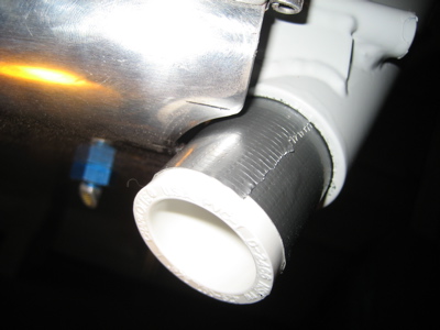
After three or four iterations with the Dremel tool and various forms of scotchbrite, I was able to get a nice uniform clearance all the way around. I should add that since I had to lay on my back underneath the airplane while I was doing this, I got aluminum and steel "snow" all over me in the process. Yuck. I wore safety gear and took a shower right afterwards so it wouldn't get into my eyes.
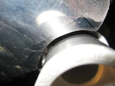
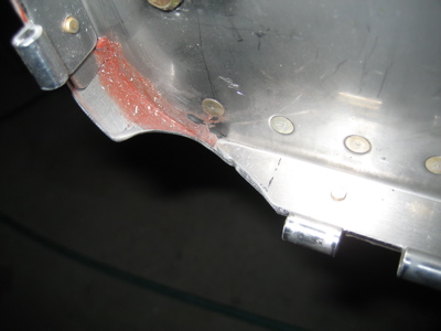
Here's the shape of the finished cutout. You can see that the outermost rivet hole is entirely obliterated. If I had waited to install the lower cowl hinges until after I'd finished these cutouts I could have saved myself an extra inch of hinge material, but oh well. I suppose I should be grateful that the amount you're required to cut isn't another 1/8" deeper, or else it would start chewing into the firewall itself.
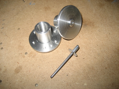
Another small puzzle I spent some time looking at tonight is the location and nature of the static ports. The plans would have you put a pop rivet into the fuselage skin on each side of the airplane, then pound out the mandrels and glue the ends of the plastic static tubing over the resulting hollow rivet shafts. Uh, no thanks. I had that setup on my last RV, and it gave me terrible static leaks until I replaced the cheesy rivets with a pair of Cleaveland static ports. I have a pair of nice looking machined static fittings (see photo below) that I picked up from Safeair in a moment of weakness, but I've heard of people having problems with them because they don't stick out far enough into the slipstream. It turns out that a static port that's too close to being flush with the skin doesn't do a very good job, and the Cleaveland ports stick out further than the Safeair ones. I may end up scrapping these and getting another pair of the Cleaveland ones instead.
I got as far as marking the static port locations and drilling a #40 pilot hole – one on either side of the fuselage, positioned as described in the plans. They'll be tee'd together to cancel out errors induced by side slips.
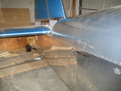
It's a loooong way back there into the tailcone where the static ports are. I can forsee this particular bit of plumbing is going to be a real joy to install.

More work on battery box and relays

Sunday, December 24th, 2006

What's this, some kind of new kind of device for keeping your pennies organized?

Nope, it's just the holddown strap for the battery. I cut the optional lightening holes to take away some of the mass of that hefty alunimum bar, and painted it to match the battery box just because I felt like it.

Down below, the input side of the starter relay is now connected to the output side of the master relay via a copper bus bar.

Interestingly, the prescribed mounting orientation for the starter relay is such that positive G forces will tend to open the relay instead of forcing it closed – there's a note in the plans about this. I guess they are concerned that the starter might kick in at the bottom of a loop?