Archive for the ‘Firewall Forward’ Category

Preparing to attach engine

Saturday, February 9th, 2008

Per the plans, I'm using Permatex #2 sealant on all threaded plumbing that attaches to the engine:

I had to remove the oil filter to install the fitting for the oil cooler return line:

With the filter back on, there appears to be plenty of clearance to get a hose onto this fitting without hitting the filter or magneto. The plans say to use a straight fitting here, but a 45-degree fitting is really necessary if you have an angled oil filter adapter like I do.

A crow's foot wrench came in handy for tightening the fitting for the other oil cooler line. A 45-degree fitting is necessary here too, as others have discovered.

Looking from the left side of the engine, you can see how the hose will go between the prop governor bracket and the engine-driven fuel pump. I may also have to use a hose with a 45-degree fitting on the end – we'll see.

Looking into the business end of a VA-128 restrictor fitting. The end is plugged with a brass (?) insert that has a small passage drilled through it. Using these for the oil and fuel pressure pickups is a smart idea, so that a broken transducer hose won't dump all your oil overboard or pump fuel onto the hot exhaust pipes.

The oil pressure fitting has to be clocked at a 45-degree angle to vertical, so the hose goes the right way and doesn't hit the engine mount. Notice I had to remove one of the clips that attaches the right magneto drive pad cover plate, in order to get a wrench on the fitting.

I propped up the tail with a sawhorse padded with foam rubber. The tailwheel spring is secured to the sawhorse with a bungee cord so it doesn't accidentally get knocked off.

Now the fuselage is roughly level, which will make hanging the engine easier.

I manhandled the engine pallet up onto dollies, and rolled it over towards the front of the fuselage:

Then I levered the whole works up onto the feet of the engine hoist. I'll unbolt and discard the pallet once my helper arrives tomorrow.

Heavy red thing is ready to attach to white thing.

Installed prop governor

Wednesday, February 6th, 2008

Here's the propeller governor, a PCU500X. This guy is basically an speed-controlled oil pump, which controls the pressure of the oil being pumped through the hollow crankshaft, and thus sets the pitch of the propeller blades to hold the desired RPM. I started to explain this to Mary but she was too distracted to endure another of my lectures about aviation theory, so I just told her "it costs a thousand dollars and makes the airplane go like hell."

I had to cut off the safety wire, loosen the screws, and rotate the shaft to the correct angle to fit Van's cable bracket. Here it is after I redid the safety wire:

I used my cool new Milbar reversible safety wire pliers to twist the new lockwire, and I must say the improvement in my safety wire workmanship is noticeable compared to when I was using the old, cheap pliers. I guess once again I learn that quality tools make a difference.

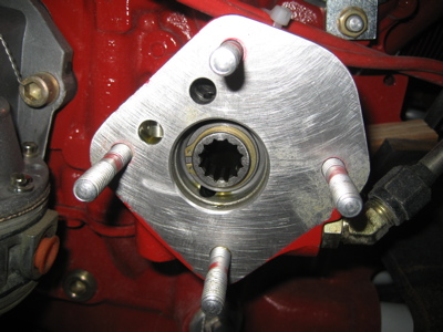
I wiped down the surface of the governor drive pad, and removed the caps covering the drive gear and the oil ports:

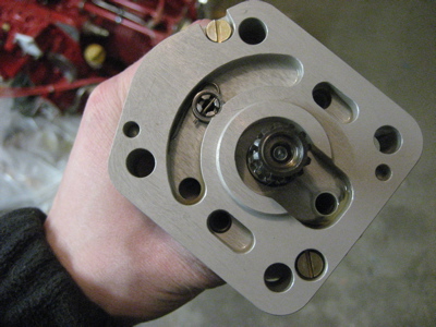
Likewise, I cleaned the mating surface on the governor and removed the plastic plugs from it too. I made sure to take these photos so I don't have to wonder, "did I really remember to remove those plugs before I bolted on the governor?"

The instruction sheet that comes with the governor says to coat both sides of the included gasket with "a suitable release agent". I dithered on this for a while before finding an old RV-List posting mentioning that Van's preferred substance is plain old fuel lube. I guess the idea here is to make it possible to remove the old gasket if you have to remove the governor, and not to put something on there to enhance the quality of the seal (e.g. Permatex).

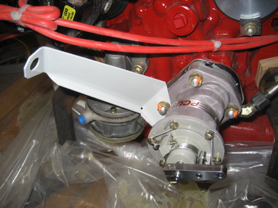
Then I bolted the governor and cable bracket to the engine, using star washers under the nuts. Due to the clearances involved I had to use a crow's foot on my torque wrench when tightening the nuts, but that was no big deal.

Here's the model info and serial number, in case I ever need it:

Engine stuff

Wednesday, February 6th, 2008

Still waiting on one last box of parts to arrive before this weekend's building session, but in the meantime I spent some time getting familiar with the engine and planning what I need to do before I bolt it to the airplane.

Here's a view of the accessory case on the back of the engine. Clockwise from the left we have the left magneto (black thing with red wires coming out of it), oil filter, vacuum pump drive pad, right magneto drive pad (unused, covered with a circular plate), prop governor drive pad (with cable bracket in place for a test fit), and engine-driven fuel pump (silver thing with blue fitting cap). The hexagonal silver thing in the approximate center of the accessory case is the vernatherm valve (basically an oil thermostat). Above and to the left of the vernatherm is the oil temperature transducer port, directly above is the tach drive pad, and below and to the right is the supply port to the oil cooler.

Closeup view of the right side of the accessory case, showing the vacuum pump and magneto drive pads, and the supply port to the oil cooler. Also visible is the port for the oil pressure gauge – it's the small hole with a red plug threaded into it, just above the magneto drive pad. (Sorry, all my pipe plugs are the same color as the engine itself, which makes them not photograph well)

Closeup view of the left side, looking past the magneto. Here you can see the return port from the oil cooler, which hides behind the oil filter. In fact I'll probably have to remove the filter to get a fitting on there.

Since this engine has a right-angle oil filter adapter, it uses a CH48108-1 filter, which has a built-in check valve. That should help keep oil changes from becoming a major environmental hazard, which has not always been the case with other airplanes I've owned. These filters are also about ninteen bucks each, but that's aviation for you.

Firewall passthrough

Sunday, November 4th, 2007

I used my Greenlee punch to put a 1 1/8" hole in the upper starboard corner of the firewall:

…through which I then installed a firewall passthrough fitting from SafeAir. Read this article from Bob Nuckolls for the background on why you'd want to bring wires through the firewall in this way. I also squirted some Biotherm firestop sealant between the fitting and the firewall, the better to keep fumes out.

The fitting has a nice radius on the aft side, so it won't chafe my wires. I'm planning to bring all the heavy electrical wires through here, and possibly the Lightspeed ignition wires as well if the routing works out. The small-signal stuff will all go through a separate passthrough, to prevent inductively coupling noise from the power/ignition wires into the sensor leads.

There's a different and somewhat similar stainless firewall penetration kit sold by EPM-AV (whose site is unreachable at the time of this writing) which I actually bought before I decided to use the SafeAir kit instead. Here you can see that the EPM fitting is made of rolled and welded stainless sheet, instead of being a one-piece spun part like SafeAir has.

Call me crazy, but I just don't like the idea of having sharp edges near my wires. Add to this the fact that the SafeAir kit is more complete, uses a hole size that I already have a punch for, and is slightly cheaper, and I know which one is my favorite.

Firewall wiring

Saturday, October 27th, 2007

Today I did some more firewall-forward wiring. For all the "big" wires, I'm using double-wall heatshrink tubing over the crimp terminals. This stuff is like normal heatshrink, plus an extra layer of hot-melt glue inside. It provides a lot of extra mechanical stability, which I like.

I ran a 10 gauge wire from the always-hot side of the master contactor to the battery bus fuse block:

A short jumper wire connects the battery to the hot side of the E-bus relay. Note the use of all-metal hardware… no nylon nuts forward of the firewall.

Some more short little jumpers connect the switched side of the E-bus relay to the two midi fuseholders, shown here with fuses installed.

At the bottom of the firewall, I installed the ANL fuses and finished connecting everything together with copper bus bars. I ended up removing the rubber terminal boots I had on here before, as they were pretty unwieldy (as in hard to scrunch out of the way while tightening the mounting hardware).

I decided to wait on mounting the big fuseblocks inside the cockpit until I get my radio stack installed, so I can figure out where to run the big wires without having them interfere with the radio trays.