Archive for the ‘Firewall Forward’ Category

Aux alternator and tach drive cap

Tuesday, April 1st, 2008

I've been playing with engine control cables but they're giving me fits, so no photos until I figure out what I'm going to do. In the meantime, I decided to take a break from control cable hell and install the B&C SD-20 standby alternator.
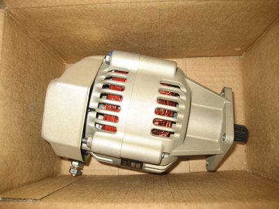
The SD-20 is gear-driven, and installs on the vacuum pump drive pad on the engine accessory case. I removed the drive pad cover plate and cleaned off the old gasket sealant in preparation for mounting the alternator.
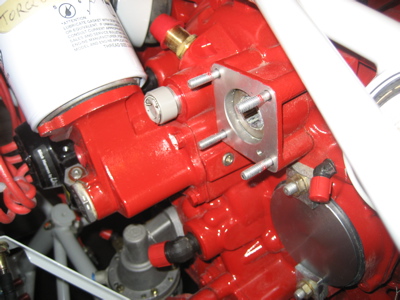
I used a crow's foot adapter on my torque wrench to tighten three of the nuts – the last one was impossible to reach with the torque wrench, so I used a plain wrench and tightened it by feel.
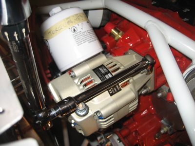
The alternator, installed:
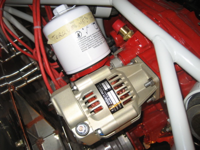
In the photos above, you can see the cap that I put on the tachometer drive gear. I actually installed it a week ago, but since Mary was out of town with the camera I'm only just now getting around to taking pictures of it. Here's a closer view:

Between the oil filter adapter and the standby alternator, there's just about zero room to install a traditional mechanical RPM sender on this engine – I'll probably use a Hall effect sensor on the mag instead. Here's another view from a different angle, showing how I safetied the cap:
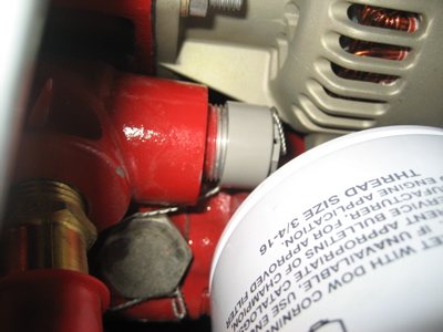
I read somewhere that it's actually optional to cap off the tach drive if you're not going to use it, but I'm just not cool with leaving a hole into the engine's whirling guts uncovered.

Throttle quadrant cable bracket

Sunday, March 16th, 2008

To attach the engine control cables underneath the panel, I made this little bracket out of 2"x2"x1/8" aluminum angle. The three small holes are for the cables, and the other holes are just to lighten it a bit.

Because the bracket will be somewhat visible hanging down under the panel (at least when you're standing on the ground behind the wing looking in) I decided to paint it black. The paint was taking forever to dry in the cold garage, so I laid the bracket on top of my little electric radiator, using a piece of scrap alclad as a tray. It cured fully after just a couple hours in the sauna.

Here is the cable bracket clecoed to the throttle quadrant supports. The green cable is from Van's and the clevis ends are from Aircraft Spruce (the clevises that Van's sells won't work).

Another view. I had to have at least one cable on hand so I could know where to mount the bracket, but without mounting the bracket I wouldn't know what length of cables to get. I chose to solve this dilemma by buying one cable in a standard 48" length, and using it both to locate the bracket and to determine how long the real cables actually need to be. Since it's a standard length, I can return it for 90% credit later, and I don't have to waste money trial-fitting with expensive custom cables that can't be returned if I guess the wrong length.

I hooked my test cable up to each of the three engine controls in turn. Here's a view of how the prop cable is routed from the eyeball in the upper-left corner of the firewall, down to the prop governor bracket. With this part adjusted correctly, the portion of the cable inside the fuselage needs to be a few inches longer.

The throttle cable comes through the firewall low and in the middle, and runs up to the bracket I previously bolted to the sump.

Inside the fuselage, the throttle cable is about an inch too short:

I forgot to take a picture of the mixture cable, but you get the idea of how this process went. In the end, I decided I needed cables that were 49", 51", and 52" long. I called Van's to order these and found that they also have standard-length cables in 49.5" and 52.5" lengths… the cable lengths can be varied somewhat, so I decided to order those two standard lengths and one custom 51" cable.

By the way, these cables come with a most interesting label on them:

Not for use on aircraft indeed.

Mounted fuel servo

Saturday, March 1st, 2008

Mattituck sent me a new gasket to replace the wrong-sized one they'd originally sent me with the engine, so I was finally able to bolt the fuel injection servo to the engine. I put a thin coat of fuel lube on both sides of the gasket before installing it.

There aren't really any detailed instructions on how to mount this thing, other than a drawing in the plans that shows the correct orientation. In one of the bags of stuff that came with the engine I found some 5/16" nuts and star washers, so that's what I used to attach the fuel servo to the sump. Confusingly, the Lycoming overhaul manual calls out a torque value for 5/16" nuts that's noticeably higher than what AC43-13b says to use, but it's largely a point of academic interest – even using a crow's foot, there's no possible way to get a torque wrench onto at least two of the nuts, so I just wrenched them all by feel until they were good and tight.

Looking down the business end of the air intake, you can see the four airflow pickups (or whatever they're really called) in front of the closed throttle plate. The Bendix fuel injection system is a purely mechanical system, in which the amount of fuel metered to the cylinders varies with throttle position and the rate of air flow measured at the intake. It's a simple design that's been around since the 60's, and based on my experience flying other Bendix-equipped airplanes it all seems to work pretty well if it's properly set up and adjusted.

To keep unwanted junk from getting lodged in the intake throat, I covered it up with masking tape:

Bolting stuff to the engine

Sunday, February 17th, 2008

This is the Precision Airmotive RSA-5 fuel injection servo. I need to get this guy bolted onto the airplane, but it didn't come with any instructions – so I don't know, for example, if I need a gasket between the servo and the oil sump, or what. I sent an email to Mattituck.

Van's makes a pretty well-done little kit that contains a bellcrank for connecting the mixture cable to the fuel servo, and a series of little brackets for anchoring the control cables to the engine. I removed two of the case bolts and attached the bellcrank bracket to the oil sump, like so:

The mixture cable bracket attaches via another pair of case studs, underneath the #4 cylinder. These nuts all have lockwashers under them.

The throttle cable bracket bolts to a threaded boss on the bottom of the oil sump. I safety-wired the bolt heads:

Those coarse-thread bolts didn't come drilled, so I had to use my handy bolt-head-drilling jig to do it myself:

Here we go, two drilled-head, coarse-thread bolts:

I attached the engine-driven fuel pump's inlet fitting:

…and the outlet fitting, with restrictor fitting to feed the fuel pressure transducer:

Hung the engine

Sunday, February 10th, 2008

With the engine suspended from the hoist, we unbolted and removed the pallet, leaving the engine swinging:

Matthew Brandes and his foreign-exchange student Nat came up to help put the engine on. Matthew has already been through this exercise on his RV-9A, so he is an old hand. We maneuvered the engine into place and managed to get the first three bolts in without much trouble, but the last one was kind of a goat-rope.

Chad was there to help too. Maybe he'll get started on his own RV soon…?

Finally, all four bolts went in. We unhooked the hoist and lowered the tail down before final-tightening the nuts.

I was able to get all four cotter pins put in, and considering that there's almost no access to install them, I'm happy with how they turned out.

The fuselage is on the wheels with the engine installed. Awesome.

The prop governor oil line comes pretty close to the engine mount. I'll have to keep an eye on this.

The oil filter looks like it's trapped forever, but there's just enough room to remove and reinstall it.

It took about an hour and a half for us to get the engine bolted to the mount, and another hour or so for me to get the bolts tightened, install the cotter pins, and clean up. All in all, much less work than I thought it would be. Thanks to Matthew, Nat, and Chad for the help.