Archive for the ‘Empennage’ Category

Working on top rudder fairing

Saturday, February 17th, 2007

I decided that I should work on the empennage tips next, because it will be a lot easier to mess with them while I have the tail removed from the fuselage. Once the engine goes on I'll have to keep the tail attached to prevent the fuselage from tipping over on its face, so I'm trying to get as much done on the empennage while I have the opportunity.

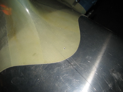
For no particular reason I decided to start with the top rudder fairing. I trimmed the flanges enough to get the part to fit onto the rudder, and match drilled #30 holes through the skin into the fiberglass.

It isn't a terrible fit, although it is quite a bit shorter than it needs to be. I'll have to build up the forward face with filler.

The plans have you attach the fairing to the rudder skin with flush pop rivets. A lot of people use filler to make their fairings match the contour of the empennage surface, then use a layer of fiberglass to hide the joint between the aluminum skin and the composite fairing. Me, I really like the look of a well-fitted fairing with a perfect, visible seam between the two parts, so I decided to steal Randy Pflanzer's method. He made his fairings removable by using 4-40 screws and nutplates instead of blind rivets, which lets you take the fairing off to clean up the join line.

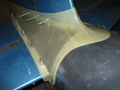
I riveted nutplates to the fairing, using a thin strip of alclad as a backing strip to keep the rivets from pulling through the fiberglass. On the first side I did (facing down in this photo) I used the same rivets to attach the nutplates to both the aluminum and the fiberglass. That turned out to be a pain to do properly, so on the other side I first riveted the nutplates to the aluminum strip, then riveted the strip to the fairing with one rivet between each pair of screw holes. That way turned out a lot better, since I could do the tricky riveting of those tiny little nutplates out in the open where I had better access.

By the way, the gaps in the alclad strips in the photo above are there because I made the them out of scrap and I didn't have anything long enough to span the full length of the fairing.

Here's an initial view of how the fairing looks when screwed in place. A #4 flush screw fits in the same dimple as a 1/8" rivet, and I really like the look of the visible fasteners. There is about a 1/16" gap along the join line, which will need filling.

I protected the rudder skin with a layer of electrical tape (very thin but rugged enough to resist sanding) and some duct tape too for good measure. Then I used some 60 grit to knock down the high spots in the fairing. The very tail end was the worst spot, as the fairing was quite a bit thicker than the rest of the rudder back there.

Then I mixed up a batch of epoxy and microballoons that was about the consistency of peanut butter, and slathered it all along the join line, making a special effort to try and force it down into the gap. I also tried to build up a big glob of filler on the forward face where the fairing is too short, but I expect I'll have to revisit it a couple more times in order to get enough material where it needs to be.

I'll let the whole mess dry overnight, then sand off all the excess and see where it leaves me.

Oh yeah, while I was doing stuff in the airplane workshop I installed the eye bolts through the firewall, to which the rudder pedal return springs will attach.

Started removing the tail

Sunday, February 11th, 2007

I decided that I'd better get the tail permanently mounted before the engine arrives, since without the weight of tail back there the engine will tip the airplane over. But before I can put it on for good, I need to take it off once more in order to finish up a few chores. Tonight I got as far as removing the vertical stabilizer.

I squeezed the remaining rivets on the rudder stops that were previously blocked by the VS spar. I also smoothed out a few scratches in the aft bulkhead that were a result of the initial stabilizer fitting. Looks like the primer dripped – doh.

I attached the nutplates for the fairing to the vertical stabilizer:

…and one to the fuselage just in front of the tail:

Working on empennage fairing

Saturday, December 9th, 2006

I got the empennage fairing out again and continued playing around with it. Here it's clecoed to the tail using the holes I'd previously made:

There's a ton of extra material to be trimmed off where the fairing wraps around the leading edge of the horizontal stabilizer. Then the gap underneath the stabilizer is closed by aluminum cover plates. You're sort of left to your own devices to figure out exactly how to make the front part of this come out looking nice.

I had to trim a fair amount off of the F-794 cover plates to make them fit. Maybe I can sell the scraps as aluminum curly fries.

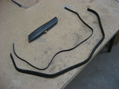
The kit comes with some rubber weather strip type of stuff, which you have to trim down.

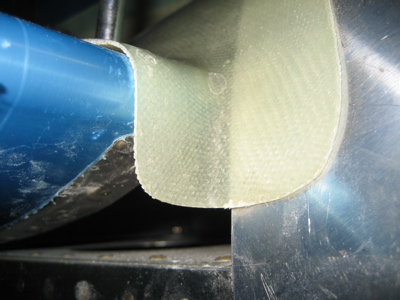
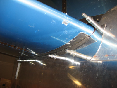
Here's one of the cover plates with the rubber strip on it. It's clecoed to the fuselage through some rivet holes in the longeron and bulkhead that I had to drill out. I wish the quickbuilders had left those holes open, because it's somewhat difficult to get under there and drill them out with the stabilizer attached, but oh well. It's hard to get the rubber strip to go completely around the curved are in the front, so I sized the cover plate piece to almost touch the stabilizer in that area instead.

Here I've trimmed and sanded away the excess fiberglass of the fairing at the forward corners (ignore the sharpie lines, I was using them to test various ideas). As you can see, there's only a very small area that's not covered by fiberglass, aluminum, or rubber. It's on the bottom of the airplane so you'll never see it. Good enough.

I also finished the cutout for the elevator horns, and sanded the aft edges of the fairing to be even with the edges of the vertical and horizontal stabilizer skins.

Because the front part of the vertical stabilizer is offset to the left (i.e. right rudder) the center of the fairing doesn't sit on the centerline of the fuselage. I eyeballed this spot for a screw and nutplate on the forward lip.

Interestingly, in the spots where the fairing attach screws go into the fuselage longerons, the plans call for you to just tap the hole in the longeron instead of installing nutplates. I used to have problems with the screws backing out in this area on my old RV, so I'm wondering if it would be worth the extra trouble to use nutplates back here (because nutplates have a self-locking feature to secure the screws). May need to call Van's to make sure the extra rivet holes in the longeron wouldn't be a strength problem. At first glance it looks like there would be plenty of room between the nutplate rivets and the next rivets over.

Worked on pitch controls

Monday, September 4th, 2006

Not much got done on the airplane today because I was tired. However, I did figure out what was wrong with the F-789 forward elevator pushrod… it's not that it was too short to allow sufficient down elevator travel, it's that the control column was hitting on the seat ribs. I dremeled out some small bites from the F-716 seat ribs, just enough to allow full forward stick plus about 1/16" extra for clearance.

Another photo of the other side. The duct tape is to protect the finish on the control column.

I likewise had to trim the removable parts of the two center seat ribs:

Once I had full stick travel, I put in the pilot's stick and seat in order to adjust the neutral stick position. Man, these seats are comfortable as heck.

Here's me doing ergonomics testing. I was in and out of the fuselage a half dozen times before I got it the neutral point adjusted where it fell easily to hand. The pushrod has a little more than the minimum required thread engagement, which is good. If you're reading this and you haven't fabricated your F-789 yet, do yourself a favor and make it about 1/4" longer than what the plans call for.

Yes, I made airplane noises:

Made rudder stops

Sunday, September 3rd, 2006

If I worked at a real airplane factory, I'd get fired for taking like eight hours of work over two days to make these stupid little rudder stops. Of course it doesn't help that the design requires each set of stops to be tailor-made to the individual aircraft. I spent a huge amount of time measuring, making and discarding test pieces, and fiddling around with templates. Out of absentmindedness or frustration I forgot to take any photos of this process, so here's a shot of the first rudder stop I was able to produce that actually fit:

You can see that I've temporarily installed the rudder cables to make sure that the rudder stops and cables don't get tangled up at any point along the full swing of the rudder.

Here's an overexposed overhead view showing the angle the rudder horn is at when it hits the stop. Lots of cutting and filing to get to this point.

It means nothing unless it has that swing – when the rudder hits the stop and the elevators are neutral, it's just a shade over an inch from the rudder to the inboard corner of the elevator trailing edge. Plenty of clearance to keep the tail surfaces from banging together, and slightly more travel than is called for in the plans. Extra rudder travel is good, it means extra rudder authority. I've heard of some people making this dimension more like 1/2", but that seems like cutting it bit fine to me.

After I was finally satisfied with the fit, I rounded off all the corners and made the stops look pretty, and countersunk the rivet holes. These two I was able to do with the countersink cage; for the two that are closer to the flange, I used this setup to make the countersinks freehand.

I primed the stops and the skin underneath, then riveted them halfway on. The plans call for CS4-4 blind rivets in the front two holes. I used CherryMax CR3212-4-4's instead since I have a whole drawerful; the literature says they are something like 3x stronger in shear. The aft two holes will have to wait for now, since I can't squeeze those rivets until I remove the vertical stabilizer.

This photo is to remind me that I haven't torqued any of the control surface jam nuts yet – my torque wrench has a 1/4" drive and my crow's foot wrenches take a 3/8". Time to go to Sears!