Archive for the ‘Electrical/Panel’ Category

Starter & alternator cables

Sunday, August 14th, 2011

I got the big cables run for the starter and primary alternator. Here's an overview shot, and I'll walk you through the details below:

I played around with several different variations of cable routing before I found a configuration I liked, which took several hours. Then I had to take it all apart, cut the cables to the proper length, and install the terminal ends with my crimping tool in the vise. This is 4 AWG wire in this photo.

Good thing I didn't forget to install the current sensor on the alternator cable before I crimped on the ends. Proper clocking of the terminals is important here too.

Young Ryan from work stopped by for a visit, and I put him right to work. An extra set of hands is… handy!

We made a spike catcher diode for the starter contactor out of a 1N5400 I had laying around. The anode connects to ground through one of the mounting bolts, and heatshrink insulates it all.

Here begins the tour. The starter cable leaves its contactor and heads towards the right side of the firewall (left in this picture). The alternator cable comes off the big current limiter, goes through the current sensor, and continues on in the same direction. You can also see the much smaller alternator field wire, which comes in from the top and parallels the whole works. Adel clamps are everywhere, holding the big cables securely.

This may be my crowning achievement in adel-clampery. Three clamps on the same bolt hold both the starter and alternator cables to the engine mount, and another adjacent pair holds the alternator current sensor. If you've ever dealt with adel clamps, you can imagine how fun it was to install all of this.

The two cables meet up at another set of clamps on the starboard gear socket:

Then they turn the corner and run in parallel through space up to the engine. I left a bit of slack to accommodate relative movement between the engine and the fixed components.

The wire bundle is clamped to the #3 cylinder induction tube and then runs forward from there.

The wiring runs along the top of the oil sump towards the front of the engine. It's hard to see, or even to photograph properly, but the exhaust pipes are nowhere near the wires – the pipes are at least three inches outboard, not visible in this photo.

Adel clamps attached to convenient sump bolts bring the wires around the corner and back around towards centerline. There's adequate clearance between the wires, oil sump, and prop governor line, and the wires are secure enough to avoid chafing.

The alternator cable then splits off and does a 180 back towards the alternator. A clamp on the bolt that holds the prop governor line in place keeps the cable from flopping around and rubbing against the nearby fuel hose.

This is a view of the same area, looking upward from below:

I put a knife splice joint and a service loop in the alternator field wire, and used plenty of heatshrink to support the wire where it goes into the (needlessly huge) plastic field connector. This seems like a prime location for a wire to fatigue and break, so I tried to secure things as well as I could.

Later on, I potted the connector with RTV to further secure the wires:

Meanwhile, the starter cable continues across to the port side of the engine, behind the starter itself (removed for this photo).

Note the clamping arrangement needed to bring the starter cable around the spine of the engine and then back up to clear the mixture bellcrank assembly. This is heavy 2 AWG wire, so you can't just bend it out of the way and hope it stays there, you have to bolt it down.

Around the back of the starter it goes, then bends forward to the starter terminal post:

From the front it looks like the starter cable must surely be rubbing on something back there, but from below you can see there's plenty of clearance between the wire and the starter housing:

No conflicts here:

I also had a rare burst of foresight, and brought out the air duct to check for interference with the starter cable. No problem here either:

It's good to have the two heaviest wires on the airplane installed for good. Just one of a million details left to do before this thing is finished…

Current sensor spacers

Saturday, July 23rd, 2011

I'm using Amploc brand Hall effect sensors (most easily found as a GRT accessory) instead of shunts to measure alternator current in my airplane. You pass the bus wire through the middle of the sensor, which is a bit less than an inch in diameter:

The wire doesn't have to be centered inside the sensor, but I still wanted to come up with a way to secure it and make it look nicer. This just looks sloppy to me:

I went up to Airparts and bought some 1" diameter nylon rod, then turned it down on my lathe so it would exactly fit the inside diameter of the current sensors. Having a lathe is great, even if I am only barely competent at using it.

With a bit chucked in the tailstock, I center-drilled the nylon to fit the diameter of the wire. After I took this photo, I parted off what I needed and cleaned up the ends a bit.

Voila, now it's a perfect fit:

I made one spacer with a 3/8" hole to fit the #4 wire from the main alternator, and another one with a 5/16" hole to fit three turns of #10 wire for the secondary alternator. With a Hall effect sensor, running multiple turns of wire through the sensor gives you a current reading that's multiplied by the number of turns, which your engine monitor then divides back down to give you the true current value. This is a handy way to increase the accuracy of the measurement, as long as your EFIS supports it, which mine does. Since these are 100A sensors, three turns of wire from the 20+ amp standby alternator should be just about right.

I glued the spacers into the sensors with E6000. Nylon is resistant to most glues, but I'm hoping this stuff will grab hold of the roughed-up surface.

Next: Off to Oshkosh for a week…

Wiring and workshop cleanup

Saturday, May 15th, 2010

I used split plastic conduit from the auto parts store to cover the exposed wiring that runs up the firewall. I have the goal of not having any exposed wires visible to the pilot or passenger, and this is an easy way to hide them. I thought about continuing the plastic stuff all the way to the spar, but it's too fat to allow the fuel pump assembly and center cabin cover to be installed.

That pretty much does it for the wiring that I'm able to finish at the present time. There are still plenty of loose ends (literally! ha-ha!) but I need to work on some other areas first. My garage was becoming highly cluttered after a whole winter of electrical work, so I spent the evening cleaning and putting away stuff that didn't need to be out anymore.

Hmm, what to do with all these spools of aircraft wire?

A hardwood dowel and a piece of scrap lumber make a handy wire stand!

It's shocking how many little plastic containers of loose hardware I have floating around the garage:

It took me a couple hours, but I reclaimed about three quarters of it all, and put each item back in its little drawer. I still have a bunch of AN nuts and bolts, which I am not returning to the general population since I don't want an old beat-up fastener to accidentally be used for something important. Plus there's a bucket of miscellaneous parts that don't have a home right now.

Plenty of room for the next project now! Although I'm sure I'll have it looking like a pig sty in no time.

Ignition power

Sunday, May 9th, 2010

The wiring instructions for the Lightspeed ignition system are full of unusual requirements without explaining the reasons behind them. I decided to deviate from the suggested schematic in a few specific ways. Disclaimer: think carefully about how you wire your ignition system, and be careful when deviating from the manufacturer's recommendations.

To provide the ignition with a redundant source of power from my aux battery, I used a pair of Schottky diodes in a handy two-in-one package. Of course, the reason for using a Schottky here is to minimize the forward voltage drop. Power Schottkys are kind of hard to find in a convenient package – i.e. with mounting holes, insulated base, and non-solder terminals – but I got a tip about IXYS products and found this diode that is more than adequate for what I need.

The big red thing is a noise filter capacitor I installed to try and preemptively deal with the reported power supply ripple that the ignition has supposedly been known to generate. This is the same 26,000 uFd cap they install with MSD race-car ignitions, so hopefully it will do the trick. It's certainly big enough. It fits pretty well on the passenger-side subpanel, which is just a few inches aft of where the ignition will go.

The Lightspeed instructions tell you to use shielded wire for all the power connections, with the shield used as the ground return. This is impractical with my setup, although I did use shielded wire for the connections from the batteries to the diodes (with the shields used in the normal fashion, and grounded to a handy screw on the subpanel). A short length of wire connects all the ignition stuff to the single-point ground block on the firewall, and I deemed the wiring from the diodes to the capacitor to the ignition to be short enough as to not require me to fool around with shielding. Hopefully all this will be enough to avoid having ignition noise in my headphones.

Last wiring task of the day was to run a length of shielded wire from the ignition over to the corresponding switch on the pilot's side of the panel. The ignition always has power, even when the airplane is off, but it has a separate "enable" input that's wired just like a magneto P-lead. Closing the switch grounds the faux P-lead to its shield, disabling the ignition. I chose to use this approach rather than switching the power input (which you can also do) because the relative locations of all the various components would require that approach to use a whole lot more wire (and current-carrying, noise-radiating wire at that).

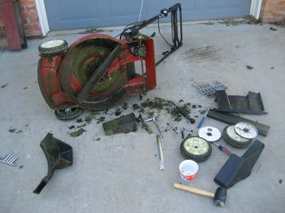
I would have spent more time working on the airplane this weekend, but I had to spend a whole afternoon fixing the mower. Grrr.

Wiring, cleanup

Sunday, April 11th, 2010

As best I can tell, I have finished running all the wires that pass through the cabin. Following a good vacuuming, I tidied up all the wiring runs under the floor and replaced the temporary twist-ties with plastic zip ties. I do love the look of an orderly wiring harness:

Everything is finished in the aux battery area. I used split corrugated wire loom where the wire bundles pass next to the battery tray, to prevent problems with chafing.

After closing out the center tunnel wiring runs, I reinstalled the aileron trim servo. The wires that will go to the control sticks don't actually connect to anything yet; that will happen later.

I used more plastic loom in the area where the wire bundle has to squeeze between the servo and the belly skin. Getting all the stuff installed in this tiny area was a (literal) pain.

Forward wiring runs all neatly bundled and secured to the floor:

Of course, up behind the panel it is a different story:

I temporarily reinstalled the fuel pump and selector valve to check the fit. The tubing runs I'd previously made, running from the bulkhead fittings in the F-783B cover support ribs to the fuel valve, won't fit anymore since the wire bundles are now in the way. I think I can work around this by using some different bulkhead fittings. Or at least I hope I can, since the airplane won't be going anywhere if I can't find a way to get fuel to the engine…