Archive for the ‘Electrical/Panel’ Category

12V socket

Monday, May 18th, 2009

I installed a simple 12-volt socket on the passenger side of the panel, for powering miscellaneous devices:

I used 14-gauge wire and a 10A fuse for this socket. A rubber boot over the positive terminal protects against shorts.

What do you think, should I use this as my backup GPS?

Headset jacks

Sunday, May 10th, 2009

This weekend's main task was to connect and install the pilot and passenger headset jacks in the brackets I'd previously made. Each occupant has separate jacks for headphone audio and microphone, plus a separate Bose jack that combines phone and mic audio plus power for my nice ANR headsets. Add in the wiring for the push to talk button, and you end up with a lot of wires that all have to be carefully soldered to the jacks. Of course all the wiring is shielded too, and you have to join multiple shields together in a couple spots. The wires that come attached to the Bose jacks are 26 gauge, which is just incredibly small and difficult to work with. I think I'm still slightly cross-eyed from sorting out all those tiny wires.

Here's the same thing tied into a nice bundle and installed in the bracket. Note that I used heavy heatshrink to support the connections.

I left generous service loops for future maintenance:

The audio connector on the GMA 347 is by far the busiest connector in the whole panel. The bundle of shielded wires going to this connector keeps getting bigger and bigger. Luckily there's just a handful of connections yet to be made on this particular connector. Man, I really overused the word "connector" in this paragraph.

I made Mary come downstairs and help me test my handiwork by talking back and forth using a pair of headsets. It all worked! Not quite Alexander Graham Bell, but satisfying anyway.

I thought I would knock out the headset jacks in an hour or two and then move on to other things… instead it took me two afternoons to finish it all. Just a lot of fiddly little things to get hooked up and working right.

Parking brake cable

Sunday, May 3rd, 2009

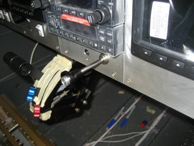
Time to install the parking brake cable… I actually had to remove the parking brake valve from the airplane, since I quickly discovered that the lever will hit the hose fitting once the control cable nut is installed. Good thing I used nutplates on the valve bracket – at least it was easy to remove.

The lever is joggled a bit, but I had to bend it further to keep it from hanging up. Seems like kind of a silly design to me.

I bought a locking cable and drilled a hole for it underneath the transponder. I briefly toyed with the idea of somehow hanging it off the side of the throttle quadrant, but this way is much easier.

The brake cable is secured with about a million adel clamps. The first one is screwed to a little flange and nutplate that I riveted to the bottom of the radio stack reinforcement angle that goes along the bottom of the subpanel.

From there, it goes forward to the bottom of the avionics shelf and turns left…

Another clamp helps it turn the corner and head upwards. It's actually not this wavy-looking in real life, it's just how it looks in a macro photo.

One more clamp sends the cable straight up, where it does a 180 and points downward to the brake valve. A final adel clamp holds the cable end, and is attached to a sloping piece of angle I ran between the F-695 fuselage gusset to the left subpanel rib.

All this elaborate routing is required because of the way the valve lever operates. When the parking brake knob is pushed all the way in, the lever is down and the brake valve is open – in other words, the brakes will work normally.

When the knob is pulled out a couple inches, like this…

…the lever is up and the brake valve is closed, trapping pressure in the brake lines and keeping the brakes applied even after you let up on the pedals. Note that the end of the cable sheath provides a positive stop to keep the lever from going over center… I'll probably replace this cushioned adel clamp with one of these later on, just so the cable can't slip.

This is all pretty simple, but like many things it's not in the plans and you're left to your own devices. The whole panel area is full of situations like this – in fact, I've been so busy doing my own thing with wiring and whatnot that I don't think I've looked at the plans for many months.

Heat control knob

Sunday, April 12th, 2009

I have been thinking for a while about what kind of mechanism to use for the cabin heat control. Although most airplanes use some kind of plunger-like Bowden cable for this purpose, I thought it would be kind of neat touch to use a rotary knob instead. Through VAF I found a gear control with cable that I thought might work, so I ordered one to try out:

It's an automotive heater control, which translates 270° of knob rotation into a couple inches of cable movement. For reference, I believe this is made by Evans Tempcon, part number RV218456. As far as I can tell, it seems to be designed for an old Grumman mail truck, and since Grumman also made a bunch of great airplanes, it's practically an aviation part already!

The cable sheath that came with it was way too thick, but I was able to replace it with the outer sheath from a spare Bowden cable I happened to have on hand. I also replaced the sheet metal screw holding the cable clip with a machine screw and nyloc nut instead. After some experimentation I decided that it might work, so I mounted it in the lower outboard corner on the passenger side:

On the crew-facing side of the panel, the knob control is held on with a nut and lockwasher (salvaged from the junk bin at work). I also drilled and tapped a hole through the panel and the steel body of the gear assembly, for a 4-40 screw to keep it from rotating.

The cable goes forward from the panel, is secured to the bottom of the subpanel with an adel clamp, and then heads uphill and outboard towards the corner of the firewall:

At its apogee, the cable is affixed to the fuel vent line with a pair of adel clamps. This is about the only clamping arrangement I could come up with that didn't involve remaking the aluminum line; it's just here to keep the cable from wobbling around, not supporting any actual load.

From there the cable goes down one of the firewall stiffeners to the heat box area. To hold this adel clamp, I used a slightly longer bolt into one of the nutplates that attaches the battery box to the firewall.

I drilled a hole in the upright firewall stiffener and ran the cable sheath through it. The heat box control arm is attached with a cable wire nut. The amount of cable travel is just about perfect for this application.

Back at the panel end, I put on a knob I got from McMaster-Carr, and whipped up a little placard in DeltaCAD (just a paper printout of it in this photo). I'll add this to the list of placards I need to have engraved or printed on vinyl for the finished panel.

Here's a wider view of the right side of the panel:

I'm pretty pleased with how this turned out. I'm trying to provide an automotive-like environment for passenger comfort, and having a heat control that makes sense to non-pilots will certainly help.

Comm antennas

Monday, March 30th, 2009

My brother helped me install the belly-mounted comm antennas while he was in town this weekend. In the photo below we're lining up the antennas and drilling the mounting holes… much easier to do it with the antennas inside the fuselage than outside:

My camera was low on batteries so I didn't get a picture, but we made doublers for the antennas out of 0.050" alclad. You can kind of see one in this photo:

Since the antennas are grounded via their mounting screws, ensuring good electrical contact is essential for proper antenna performance. I used an alodine pen to corrosion-proof all the mating surfaces:

Here's a better shot of the fuselage doublers, with the alodine drying. It looks blotchy but that doesn't really matter.

I likewise cleaned, scuffed, and alodined the areas of the fuselage floor destined to be covered by the doublers:

Adam helped me rivet the doublers to the floor:

They're also attached to the seat ribs with blind rivets – plenty strong. Each antenna is attached with four screws that go into floating nutplates, and the BNC connector protrudes through the hole in the middle.

Voila, antennas. This arrangement should make for easy wiring, keep the antennas out of the plume of exhaust gunk, and satisfy the radios' requirement for minimum antenna separation distance.